uart
11.2021

Click on images to enlarge.
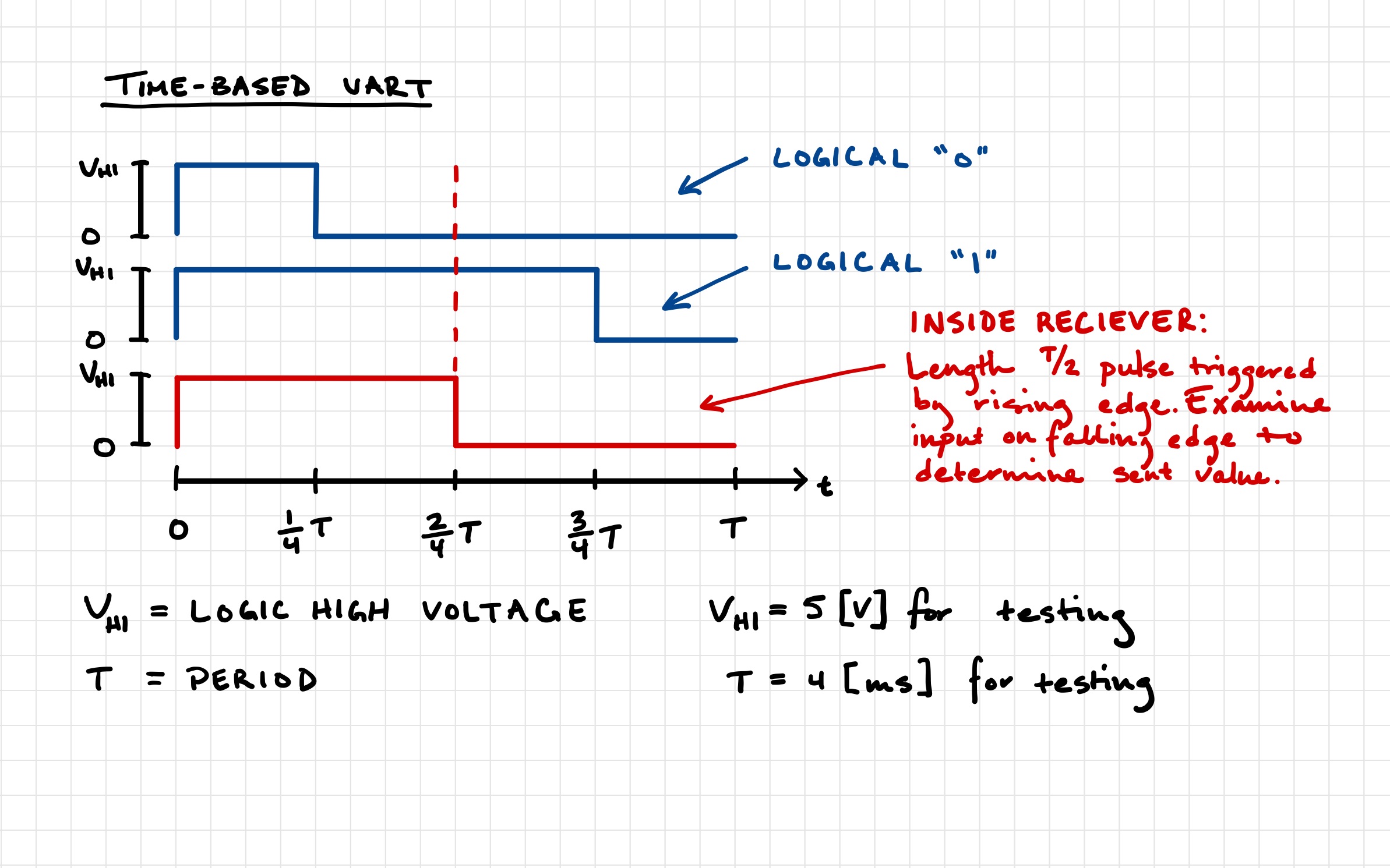
The goal of this project was to create a simple UART (Universal Asynchronous Receiver-Transmitter) device, which would be able to send digital messages over a serial interface. The standard technique of assigning boolean values to voltage was not used, instead a time-based method was used, i.e. a shorter pulse representing a logical “0”, and a longer pulse representing a logical “1”.
The mapping of logical values to time instead of voltage has a few unique benefits. Since the receiver’s clock is syncing once per bit instead of once per message, error in baud rate timing is nearly eliminated. The error for the whole message is the same as the error for each bit, instead of compounding for every bit in the message.
A two wire interface was used (ground, data), as only one receiver and transmitter were assembled for testing. This setup would simply be doubled to allow both sides to send and receive. The top breadboard contains the sender, the second contains the receiver, and the third contains a display, which shows the last eight bits received. The transmission wire can be seen with white and black stripes, bridging the first and second boards on the left side.